Writing sensory-motor loops in ROS
Today
- Coordinate Frames and Transforms
- Writing our first sensory-motor loops (in groups)
For Next Time
- Work on the
the Warmup Project . There is an intermediate checkpoint due on Tuesday (class meeting 4).
Follow-up From Last Time
Uniqueness of Node Names
ROS2 Nodes should have unique names. There is support for changing the node name when launching a node (or specifying a unique name in the launch file). If you start two nodes with the same name, the system will allow you to do it, but you will get a warning that things might go bad (ominous!). For example, I can set the name of the teleop node as follows.
$ ros2 run teleop_twist_keyboard teleop_twist_keyboard __name:=my_name
Youc an verify this worked, by running the following command.
$ ros2 node list
Coordinate Frames and Coordinate Transforms in Robotics
Likely you’ve encountered the notion of multiple coordinate systems before at some point in your academic career. Depending on your path through Olin, you may already be familiar with the mechanics of how to map vectors between different coordinate systems (either in 2D or 3D). In this exercise, you’ll get a chance to refresh some of this knowledge and to also gain a conceptual understanding of how the notion of multiple coordinate systems plays out in robotics.
Suppose your Neato is at position 3.0m, 5.0m with a heading of 30 degrees (where counter-clockwise rotation is positive) in a coordinate system called world. Draw a picture. Make sure to label the axes of the world coordinate system (don’t worry about the z-axis).
In robotics, we frequently need to express the position of various entities (e.g., obstacles, goal locations, other robots, walls, doorways, etc.). While we could express all of these positions in terms of the coordinate system world, in many situations this will be cumbersome.
Exercise: Taking the Neato as an example, make a list of the coordinate systems that you feel would be convenient to define. For each coordinate system, define its origin and give a few examples of entities that would be natural to express in the coordinate system.
base_link
Next, we’ll define base_link, which will serve as our robot-centric coordinate system. The origin of this coordinate system will be at the midpoint of the line connecting the robot’s wheels. The x-axis will point forwards, the y-axis will point to the left, and the z-axis will point up. Update your drawing to indicate the position of the base_link coordinate axes (again, don’t worry about the z-axis).
Now that we have defined our new coordinate system, we’d like to be able to take points expressed in this coordinate system and map them to the world coordinate system (and vice-versa). In order to do this, we need to specify the relationship between these two coordinate systems. A natural way to specify the relationship between two coordinate systems is to specify the position of the origin of one coordinate system in the other as well as the directions of the coordinate axes of one frame in the other. Going back to our original example we can say that the coordinate axes of the Neato’s base_link coordinate system are at position 3.0m, 5.0m with a rotation of 30 degrees relative to the coordinate axes of the world coordinate frame. We usually think of this information as defining the transformation from world to base_link. It turns out that with just this information, we can map vectors between these two coordinate systems. ROS has robust infrastructure to handle these transformations automatically, so for the most part when writing ROS code, you don’t have to worry about how to actually perform these transformations. However, to build your understanding, we’ll dig into this the details a bit.
From base_link to world
Exercise: Determine the coordinates of a point located at (1.0m, 0.0m) in the base_link coordinate system in the world coordinate system. First draw the point on the board to make sure everyone agrees what its location is. Once you’ve determined your answer, how can you tell if you are right?
Exercise: Determine the coordinates of a point located at (0.0m, 1.0m) in the base_link coordinate system in the world coordinate system. First draw the point on the board to make sure everyone agrees what its location is. Once you’ve determined your answer, how can you tell if you are right?
Exercise: Determine the coordinates of a point located at (x, y) in the base_link coordinate system in the world coordinate system. If you are having trouble operationalizing your answer in terms of equations, you can define it in terms of high-level operations (e.g., translations, rotations, etc.).
From world to base_link
There are multiple ways to tackle this one. We think it’s easiest to do algebraically, but you can do it in terms of geometry / trigonometry too. Don’t get too hung up on the mechanics, try to understand conceptually how you would solve the problem.
Exercise: Determine the coordinates of a point located at (0.0m, 1.0m) in the world coordinate system in the base_link coordinate system. First draw the point on the board to make sure everyone agrees what its location is. Once you’ve determined your answer, how can you tell if you are right?
Exercise: Determine the coordinates of a point located at (1.0m, 0.0m) in the world coordinate system in the base_link coordinate system. First draw the point on the board to make sure everyone agrees what its location is. Once you’ve determined your answer, how can you tell if you are right?
Exercise: Determine the coordinates of a point located at (x, y) in the world coordinate system in the base_link coordinate system. If you are having trouble operationalizing your answer in terms of equations, you can define it in terms of high-level operations (e.g., translations, rotations, etc.).
Possible Notation
Sometimes, it can be helpful to lead with notation. Other times, it can obfuscate and confuse. Here is some notation that I have used to reason about and deifne coordinate systems. If this is useful to you, please go for it!
\[\begin{eqnarray} \mathbf{p}_{/W} &\triangleq& \mbox{a point, p, expressed in coordinate system W} \\ \mathbf{p}_{/N} &\triangleq& \mbox{a point, p, expressed in coordinate system N} \\ \hat{\mathbf{i}}_{N} &\triangleq& \mbox{a unit vector in the i-hat direction of coordinate system N} \\ \hat{\mathbf{j}}_{N} &\triangleq& \mbox{a unit vector in the j-hat direction of coordinate system N} \\ \hat{\mathbf{r}}_{W\rightarrow N} &\triangleq& \mbox{a vector pointing from the origin of W to the origin of N} \\ \mathbf{r}_{W \rightarrow N / N} &\triangleq& \hat{\mathbf{r}}_{W\rightarrow N}\mbox{ expressed in coordinate system N} \\ \hat{\mathbf{i}}_{N/W} &\triangleq& \hat{\mathbf{i}}_{N}\mbox{ expressed in coordinate system W} \\ \hat{\mathbf{j}}_{N/W} &\triangleq& \hat{\mathbf{j}}_{N}\mbox{ expressed in coordinate system W}\end{eqnarray}\]Static Versus Dynamic Coordinate Transformations
The relationship between some coordinate systems are dynamic (meaning they change over time) and some are static (meaning they are constant over time).
Exercise: Assume that our Neato robot can move about in the world by using its wheels. Is the relationship between world and base_link static or dynamic? Given the coordinate systems you came up with earlier, list some examples of coordinate system relationships that are static and some that are dynamic.
Before Starting
Sensory Motor Loops
One way to think of the intelligence that drives a robot is as a sensory-motor loop.
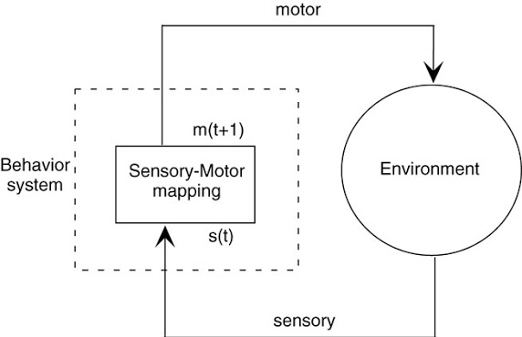
Today, we will be building on the basic ROS nodes we wrote last time to create a ROS node that both integrates sensory data (through subscribing to a topic) and outputs a motor command (by publishing to a topic).
Creating our First Sensory Motor Loop
Sample solutions to this can be found in the
class_activities_and_resourcesGithub repository underin_class_day03_solutions. (if you are looking for the C++ solutions, look in the directoryin_class_day03_cpp_solutions).
Find another person in the class to work with. If you’re paired up for the warmup project, consider working with that person. In pairs, you will begin to explore the idea of a sensory-motor loop on the Neatos.
In order to get started, create a package for the code that you will be writing today. As with all ROS packages in your workspace, it must be inside of your ros2_ws/src folder. Besides this requirement, you are free to put the package anywhere.
$ cd ~/ros2_ws/src/class_activities_and_resources
$ ros2 pkg create in_class_day03 --build-type ament_python --node-name emergency_stop --dependencies rclpy std_msgs geometry_msgs sensor_msgs neato2_interfaces
The first sensory-motor loop we will create is one in which the robot moves forward at a fixed speed until it senses an obstacle (using the bump sensor) and then stops. For a rundown of the bump sensors on the Neato, check out the
Hints:
- You will need some way to share data between the callback functions that process the Neato’s sensory data and your main robot program. Assuming you are using classes to define your ROS nodes, you can create a class attribute to share this data between class methods..
If you execute the ros2 pkg create command given above, there should already be a file called emergency_stop.py created for you. If you placed your package in ros2_ws/src it will be located at: ~/ros2_ws/src/class_activities_and_resources/in_class_day03/in_class_day03/emergency_stop.py.
Using the Laser Range Finder
The next sensory-motor loop I suggest that you create should be called distance_emergency_stop.py. In order to add this node, you will have to modify the setup.py file in your in_class_day03 package.
The distance_emergency_stop.py node should be identical to emergency_stop.py except it should use the laser range finder to detect when an obstacle is within a specified distance and stop if this is the case. It is up to you how you implement this. You can either use just the measurements in front of the robot, or perhaps use all of the measurements. You may want to use an all-or-nothing control strategy (also called bang-bang) where you are either going ahead at some fixed speed or you stop completely. Alternatively, you may use something akin to proportional control where your speed slows proportionally with how close you are to the target distance. Again, for more detail on using the Neato sensors (including the laser range finder), see the
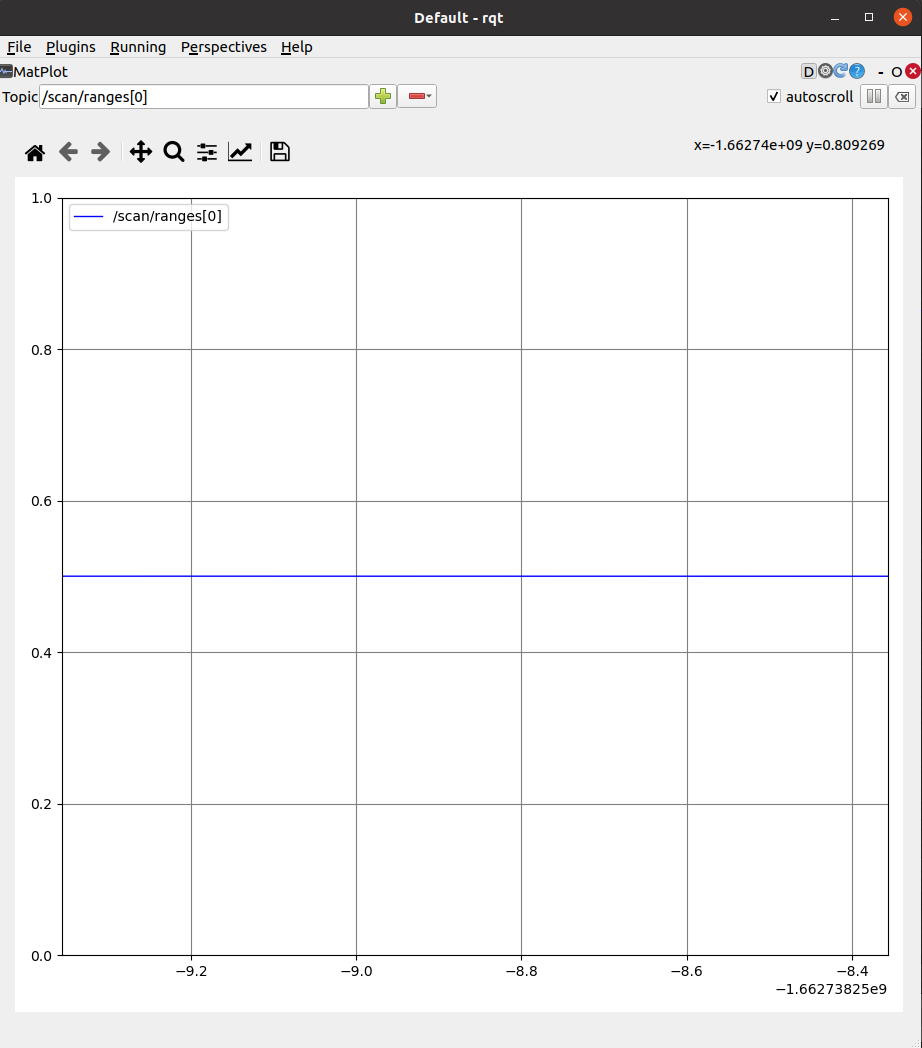
Once you implement this, you may consider using the command line tool rqt to add a visualization of the laser scan data. This plot shows scan/ranges[0] (the measurement straight ahead). For my implementation I used 0.5m as my target distance.